Description
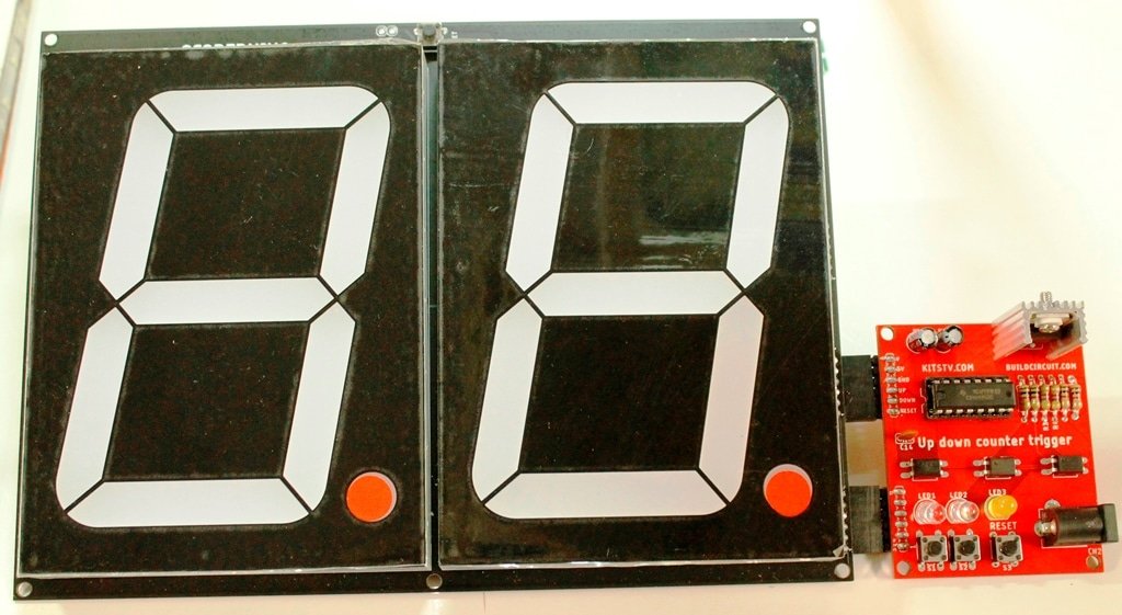
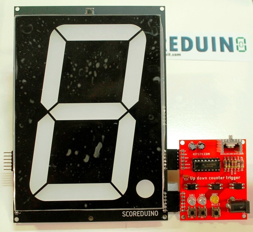
The ‘basic trigger module’ works as a basic controller for up and down counters or seven-segment display drivers. It has 3 switches for up count, down count, and reset. Up switch increases the count and down switch decreases the count and the reset switch resets the count to zero.
How does it work ?
All seven segment display drivers are designed in such a way that this basic trigger module fits into the female headers of the drivers. The UP, DOWN and RESET pins of its trigger module connect to pins 5, 4, and 14 respectively of the 74LS192 chip that contributes to up, down, and reset of the count.
When you press the tactile switches, the corresponding LEDs placed right above the switches turn on. The two LEDs are flashing LEDs to give the trigger signal.
All the drivers are designed for COMMON ANODE seven-segment displays. It can trigger these drivers:
- 1.2 inch RED common anode seven segment display driver– works with 5V-6V.
- 1.8 inch RED common anode seven segment display driver– Works with 5V-6V.
- 2.3 inch RED common anode seven segment display driver– works with 9V.
- 3 inch RED common anode seven segment display driver– Works with 12V.
- 4 inch RED common anode seven segment display driver– Works with 12V.
- 5 inch RED common anode seven segment display driver– Works with 15V.
Components used:
- 1 x PCB
- 1 x LM7805 positive voltage regulator
- 1 x 16 pins IC socket
- 1 x CD4049
- 3 x Optocouplers
- 3 x tactile switches
- 2 x 5mm Flashing LEDs
- 1 x Normal 5mm LED
- 4 x 1K resistors
- 2 x 4.7K resistors
- 1 x DC barrel
- 2 x 6 pins angle header to connect to the drivers
- 2 x 10uF electrolytic capacitors
- 1 x0.1uF ceramic capacitor
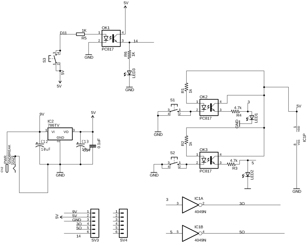
The schematic:









Reviews
There are no reviews yet.